What is a Video Digitizer?
 A Video Digitizer
is a device that takes a video image from a video camera or video recorder
(VCR) and converts it to a string of numbers. These numbers are transferred
into a computer then reconstructed back into a video image and displayed
on the computer's screen. The quality of the reconstructed image depends
on the graphic capabilities of the computer. Once the image is in the computer,
it can be processed in many ways. The most popular use for a video digitizer
is simply for creating picture slide shows. More useful applications include
the creation of clip art or pictures for desktop publishing, title graphics
for programs or amateur video, and graphic animation. A Video Digitizer
is a device that takes a video image from a video camera or video recorder
(VCR) and converts it to a string of numbers. These numbers are transferred
into a computer then reconstructed back into a video image and displayed
on the computer's screen. The quality of the reconstructed image depends
on the graphic capabilities of the computer. Once the image is in the computer,
it can be processed in many ways. The most popular use for a video digitizer
is simply for creating picture slide shows. More useful applications include
the creation of clip art or pictures for desktop publishing, title graphics
for programs or amateur video, and graphic animation.
Rascan Hardware Development History
I decided that it was time I delved into some hardware design and called
upon my friend David Meiklejohn to help with the hardware side of the design.
David was an Amiga person and so I had to feed him the specifications of
the CoCo3 and what I wanted the digitizer to do. David would then design
the circuit and create the PCB layouts while I bought the parts, made up
the prototypes and wrote the software interface. The digitizer began as the
Rascan Video Digitizer. Three different designs were made of the Rascan units,
although the circuits were all basically the same.
Design 1 - Australian |
Design 2 - Game Point |
Design 3 - Supersoft |
The first unit was built in Australia on a single sided circuit board. It
was sold in Australia directly from me. It was built into a "High Tech" silver
box, had two dials on the front for the Black and White level adjust and
a power switch. Two cables emerged from the rear which plugged into the two
CoCo3 joystick ports. A video signal could be fed into a RCA type jack on
the rear of the unit and the unit powered by an internally mounted alkaline
9 volt battery.
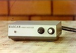
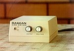
Around this time, I had just struck up a deal with Game Point Software to
distribute my games. When I told Peter Ellison, owner of Game Point Software,
that I had developed a Video Digitizer for the CoCo 3, he said that he wanted
to manufacture and market it in the US. I sent him a unit and a circuit diagram
of the design which he took to a PCB company and had a new Rascan unit made
up. The first adverts in "The Rainbow" appeared in the June '89 issue on
page 67 and advertised the Rascan unit for $159US. The new unit was made
using a proffesionally etched double sided board. Unfortunately, despite
the more advanced PCB construction, this new board ended up almost twice
the size of my single sided board. To make matters worst, the case that was
used to house the circuitry was huge! I quickly described it as "The Brick".
This unit didn't seem to work as well as my original, possibly due to the
longer length of tracks and the not-so-ideal parts placement. As it turned
out, Game Point Software got into a lot of debt, not just because of the
Rascan Digitizer but also the great expense of creating full page ads in
'The Rainbow". I'm guessing this is why they closed down.
Click HERE to see
the full page Game Point Software advertisement for Rascan.
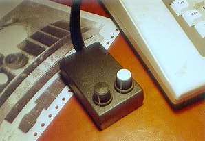
After Game Point Software came Supersoft, Inc. I had redesigned the Rascan
unit to use a more compact double sided board. I also moved the two potentiometer
controls, power switch and connectors onto the board. Supersoft advertised
this version of Rascan for $189US in "The Rainbow" , July '90 issue on page
27. I built all the units here in Australia and had them shipped to the US.
It was a lot of work to make up so many Rascan units at a time. I spent severa l
long nights assembling them, even calling over some friends to help me with
the soldering. Supersoft also developed and sold separately several printer
drivers supporting color printouts of Rascan Images.
Financially, Rascan was proving unsuccessful. It cost a lot of time and money
to produce each unit and by the end of the Supersoft distribution contract,
I had lost money on the whole deal. I felt unhappy that Rascan was not the
success I had hoped it would be but I was determined to make it work.
Digiscan to the rescue!
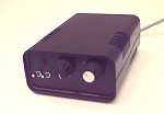
We set about redesigning the Rascan unit yet again! I wanted something that
was more time and cost effective. I went looking for a new, compact and low
cost case and found a suitable unit at the local electronics store. This
determined the size of the PCB. The box was much more compact than the previous
units meaning that David had to do a tight PCB layout for everything to fit
in.
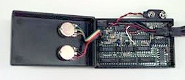 The last two Rascan units required
the additional purchase of an AC power adaptor. I wanted to eliminate this
cost so I decided to make the unit battery powered using a 9 volt alkaline
battery in the same way as the first Rascan unit. One of the main problems
with the first Rascan unit was that people were not turning the unit off
after having finished digitizing an image. This caused the battery to drain
quickly. I decided to add an extra cable from the new unit connecting to
the CoCo's cassette port, using the relay as the power switch. This allowed
the software to activate the unit only for the short period of time required
for digitizing. I also got David to work out a way of cutting out some of
the circuitry in the design and I compensated by altering the driver software.
I rewrote the entire driver software with a more proffesional graphical front
end while another "electronic genius" friend of mine, Alan Judson, helped
with some hardware debugging and fine tuning. The last two Rascan units required
the additional purchase of an AC power adaptor. I wanted to eliminate this
cost so I decided to make the unit battery powered using a 9 volt alkaline
battery in the same way as the first Rascan unit. One of the main problems
with the first Rascan unit was that people were not turning the unit off
after having finished digitizing an image. This caused the battery to drain
quickly. I decided to add an extra cable from the new unit connecting to
the CoCo's cassette port, using the relay as the power switch. This allowed
the software to activate the unit only for the short period of time required
for digitizing. I also got David to work out a way of cutting out some of
the circuitry in the design and I compensated by altering the driver software.
I rewrote the entire driver software with a more proffesional graphical front
end while another "electronic genius" friend of mine, Alan Judson, helped
with some hardware debugging and fine tuning.
So much had changed in the design that I decided to rename it to Digiscan.
Finally I had a unit which was "cleaner" in design and presentation, worked
well and cost less time and money to produce. I needed a new distributor
but this time I was going to be fussy. I needed someone I could trust and
that was prepared to pay for each unit in advance. Then, Fred Remin gave
me a call.
Fred along with his wife Roslyn were running a CoCo business called "Remcoms".
They offered to act as the Australian agent for Digiscan, selling not only
in Australia but also exporting to Farna Systems in the US. It was with this
distribution that I was able to recoup my lost money from the previous units
and make a buck or two extra. The profit was nothing to talk about but at
least I fulfilled my desire to create a successful CoCo3 Video Digitizer
and learned a thing or two about Electronic Design, PCB manufacturing, Project
Management and much more. It was a real experience and I must be honest by
saying that I enjoyed every painful minute!
The Software Interface
 |
RASCAN 2.3 / 2.4
The software driver interface for the Rascan units used overlaying windows
over the image capture area. This driver worked with only 128K RAM. All functions
were accessed via the keyboard since a joystick or mouse could not be plugged
in while the hardware was in use. |
 |
DIGISCAN 1.0
The software driver interface for the Digiscan units had separate image display
and control panel screens. It had an improved graphical level and capture
area offset adjustment. It was designed for 512K of RAM and allowed up to
8 image capture buffers which were used to create simple page flipping
animations and 4096 color images. |
 |
DIGISCAN 2.0
The Digiscan 2.0 interface was never completed. Only the graphical interface
design was developed. By this time (1993), sales for Digiscan had dropped
off and it wasn't worth investing a lot of money for more boards. I decided
that it was time to get back into some video game programming while the CoCo
was still available. |
Theory of Operation - Hardware
After a suitable video signal is fed into the Digitizer, the color component
of the signal is removed. The resulting monochrome signal then has the vertical
and horizontal synchronization pulses separated from the actual picture
information. The picture information is then send to a fast analogue to digital
conversion chip (ADC0820) and with the two potentiometers determining the
high and low (brightest and darkest) points, an 8 bit digital representation
of the signal is output. This data is then transferred to the CoCo3 via the
4 button inputs of the two joystick ports. Only 4 of the 8 bits is transferred
to the CoCo3 to derive a 16 level image.
The horizontal and vertical synchronization pulses extracted from the video
signal are used to drive the pixel clock syncronization stages. This part
of the circuit produces a pulse at a specific point along each horizontal
scan line, offset from the left hand edge of the incoming video image. When
each horizontal scanline has generated this pulse, the sweep is started again
but this time 1 pixel clock to the right of the last one. A full scan of
the screen takes approximately 15 seconds.
These pulses are used to control the analogue to digital conversion chip's
hold and modify function so that the data can be read reliably and at the
right time by the CoCo3. These signals are also sent to the CoCo3 via the
analogue joystick's X and Y ports so that the CoCo3 can stay synchronized
with the video signal. The CoCo didn't send any signals to the digitizer.
It was up to the CoCo to keep up with the digitizer!
Click HERE to view a schematic
diagram of the Digiscan Video Digitizer.
Theory of Operation - Digiscan Software
As the 4 bit video data is streaming into the computer, the software is storing
the data directly into the CoCo3's memory. Depending on the video mode selected,
the image is displayed on the CoCo's display.
16 color images are displayed "as is" with no extra processing. Since the
digitizer ignores color information, a preset palette is chosen to display
the image. This palette can be edited manually to correct the colors. The
CoCo3 can "officially" display 16 colors out of a total palette of 64 colors.
Even with 64 colors, this would be inadequate to reproduce color photo quality
images. I called these images 16 "false color" images.
When the mode is set to 16 gray, the image is processed during scanning.
In this mode, the CoCo3 is set to 640 x 200 x 4 colors and each 16 level
pixel is represented as a dithered pattern.
IMAGES CAPTURED USING RASCAN/DIGISCAN
16 "FALSE" COLOR |
16 "DITHERED" GRAY |

4096 "PSEUDO" COLOR |
4096 mode was a last minute idea I had. I figured that since I was capturing
reasonably good 16 level dithered gray images, I would try and captured 3
of these images using red, green and blue color filters on the camera lens.
I had seen this method used for the Amiga digitizers. The Amiga could mix
these three color filtered images and display them in it's 4096 color mode.
The CoCo3 didn't have a 4096 color mode so I thought I'd try displaying each
image sequencialy and synchronized with the vertical field sync of the display.
I really thought I was wasting my time and that the end result would look
dreadful. My first image was of some vegetables and the results stunned me!
I immediately decided that this mode had to stay!
Using a similar technique to the 4096 images, I added 3D image capability
(only added into the Digiscan driver software). This required taking 2 color
filtered images using the red and blue filters. The camera had to be moved
a few inches to one side for the second image. When these images were viewed
with 3D red/blue glasses, they gave the illusion of 3D!
Positives and Negatives
The Rascan/Digiscan digitizers were unique compared to most other digitizers
available for the CoCo at the time.
Some of it's main features were: Easy to use and a more proffesional user
interface, did not require a Multi-Pak Interface, and full support of the
CoCo3 graphic resolutions.
Areas where I would have liked to have added improvements but couldn't due
to cost and time were: The ability to transfer the full 8-bit image data
and improved dithering and an improved 4096 display with less flickering.
|